在 Scipy- Python中使用双线性变换方法设计 IIR 低通巴特沃斯滤波器
IIR 代表无限脉冲响应,它是许多线性时间不变系统的显着特征之一,其特点是脉冲响应 h(t)/h(n)在某个点后不会变为零,而是无限持续.
什么是 IIR 低通巴特沃斯?
它基本上就像一个具有无限脉冲响应的普通数字低通巴特沃斯滤波器。
规格如下:
- 采样率为 8 kHz
- 过滤器 2 的顺序
- 截止频率 3400Hz
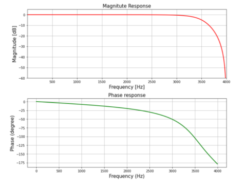
我们将绘制滤波器的幅度和相位响应。
循序渐进的方法:
第 1 步:导入所有必要的库。
Python3
# import required library
import numpy as np
import scipy.signal as signal
import matplotlib.pyplot as plt
Python3
# Given specification
N = 2  # Order of the filter
Fs = 8000  # Sampling frequency in Hz
fc = 3400  # Cut-off frequency in Hz

# Compute Design Sampling parameter
Td = 1/Fs
Python3
# Compute cut-off frequency in radian/sec
wd = 2*np.pi*fc
print(wd)  # Cut-off frequency in radian/sec
Python3
# Prewarp the analog frequency

wc = (2/Td)*np.tan(wd*Td/2)
print('Order of the filter=', N)  # Order

# Prewarped analog cut-off frequency
print('Cut-off frequency (in rad/s)=', wc)
Python3
# Design analog Butterworth filter using signal.butter function

b, a = signal.butter(N, wc, 'low', analog='True')
# Perform bilinear Transformation

z, p = signal.bilinear(b, a, fs=Fs)

# Print numerator and denomerator coefficients of the filter
print('Numerator Coefficients:', z)
print('Denominator Coefficients:', p)
Python3
# Compute frequency response of the filter using signal.freqz function
wz, hz = signal.freqz(z, p, 512)

# Plot filter magnitude and phase responses using subplot.
# Convert digital frequency wz into analog frequency in Hz
fig = plt.figure(figsize=(12, 10))

# Calculate Magnitude from hz in dB
Mag = 20*np.log10(abs(hz))

# Calculate frequency in Hz from wz
Freq = wz*Fs/(2*np.pi)

# Plot Magnitude response
sub1 = plt.subplot(2, 1, 1)
sub1.plot(Freq, Mag, 'r', linewidth=2)
sub1.axis([1, Fs/2, -60, 5])
sub1.set_title('Magnitute Response', fontsize=15)
sub1.set_xlabel('Frequency [Hz]', fontsize=15)
sub1.set_ylabel('Magnitude [dB]', fontsize=15)
sub1.grid()


# Plot phase angle
sub2 = plt.subplot(2, 1, 2)

# Calculate phace angle in degree from hz
Phase = np.unwrap(np.angle(hz))*180/np.pi
sub2.plot(Freq, Phase, 'g', linewidth=2)
sub2.set_ylabel('Phase (degree)', fontsize=15)
sub2.set_xlabel(r'Frequency (Hz)', fontsize=15)
sub2.set_title(r'Phase response', fontsize=15)
sub2.grid()

plt.subplots_adjust(hspace=0.5)
fig.tight_layout()
plt.show()
Python3
# import required library
import numpy as np
import scipy.signal as signal
import matplotlib.pyplot as plt

# Given specification
N = 2  # Order of the filter
Fs = 8000  # Sampling frequency in Hz
fc = 3400  # Cut-off frequency in Hz

# Compute Design Sampling parameter
Td = 1/Fs

# Compute cut-off frequency in radian/sec
wd = 2*np.pi*fc
print(wd)  # Cut-off frequency in radian/sec

# Prewarp the analog frequency
wc = (2/Td)*np.tan(wd*Td/2)
print('Order of the filter=', N)  # Order

# Prewarped analog cut-off frequency
print('Cut-off frequency (in rad/s)=', wc)

# Design analog Butterworth filter using signal.butter function
b, a = signal.butter(N, wc, 'low', analog='True')

# Perform bilinear Transformation
z, p = signal.bilinear(b, a, fs=Fs)

# Print numerator and denomerator coefficients of the filter
print('Numerator Coefficients:', z)
print('Denominator Coefficients:', p)

# Compute frequency response of the filter using signal.freqz function
wz, hz = signal.freqz(z, p, 512)

# Plot filter magnitude and phase responses using subplot.
#Convert digital frequency wz into analog frequency in Hz
fig = plt.figure(figsize=(10, 8))

# Calculate Magnitude from hz in dB
Mag = 20*np.log10(abs(hz))

# Calculate frequency in Hz from wz
Freq = wz*Fs/(2*np.pi)

# Plot Magnitude response
sub1 = plt.subplot(2, 1, 1)
sub1.plot(Freq, Mag, 'r', linewidth=2)
sub1.axis([1, Fs/2, -60, 5])
sub1.set_title('Magnitute Response', fontsize=15)
sub1.set_xlabel('Frequency [Hz]', fontsize=15)
sub1.set_ylabel('Magnitude [dB]', fontsize=15)
sub1.grid()

# Plot phase angle
sub2 = plt.subplot(2, 1, 2)

# Calculate phace angle in degree from hz
Phase = np.unwrap(np.angle(hz))*180/np.pi
sub2.plot(Freq, Phase, 'g', linewidth=2)
sub2.set_ylabel('Phase (degree)', fontsize=15)
sub2.set_xlabel(r'Frequency (Hz)', fontsize=15)
sub2.set_title(r'Phase response', fontsize=15)
sub2.grid()

plt.subplots_adjust(hspace=0.5)
fig.tight_layout()
plt.show()
第 2 步:使用给定的过滤器规格定义变量。
蟒蛇3
# Given specification
N = 2  # Order of the filter
Fs = 8000  # Sampling frequency in Hz
fc = 3400  # Cut-off frequency in Hz

# Compute Design Sampling parameter
Td = 1/Fs
第 3 步:计算截止频率
蟒蛇3
# Compute cut-off frequency in radian/sec
wd = 2*np.pi*fc
print(wd)  # Cut-off frequency in radian/sec
输出:

第 4 步:预包装模拟频率
蟒蛇3
# Prewarp the analog frequency

wc = (2/Td)*np.tan(wd*Td/2)
print('Order of the filter=', N)  # Order

# Prewarped analog cut-off frequency
print('Cut-off frequency (in rad/s)=', wc)
输出:

第 5 步:使用 signal.butter()函数函数双线性变换
蟒蛇3
# Design analog Butterworth filter using signal.butter function

b, a = signal.butter(N, wc, 'low', analog='True')
# Perform bilinear Transformation

z, p = signal.bilinear(b, a, fs=Fs)

# Print numerator and denomerator coefficients of the filter
print('Numerator Coefficients:', z)
print('Denominator Coefficients:', p)
输出:

步骤 6:使用 signal.freqz()函数计算滤波器的频率响应并绘制幅度和相位响应
蟒蛇3
# Compute frequency response of the filter using signal.freqz function
wz, hz = signal.freqz(z, p, 512)

# Plot filter magnitude and phase responses using subplot.
# Convert digital frequency wz into analog frequency in Hz
fig = plt.figure(figsize=(12, 10))

# Calculate Magnitude from hz in dB
Mag = 20*np.log10(abs(hz))

# Calculate frequency in Hz from wz
Freq = wz*Fs/(2*np.pi)

# Plot Magnitude response
sub1 = plt.subplot(2, 1, 1)
sub1.plot(Freq, Mag, 'r', linewidth=2)
sub1.axis([1, Fs/2, -60, 5])
sub1.set_title('Magnitute Response', fontsize=15)
sub1.set_xlabel('Frequency [Hz]', fontsize=15)
sub1.set_ylabel('Magnitude [dB]', fontsize=15)
sub1.grid()


# Plot phase angle
sub2 = plt.subplot(2, 1, 2)

# Calculate phace angle in degree from hz
Phase = np.unwrap(np.angle(hz))*180/np.pi
sub2.plot(Freq, Phase, 'g', linewidth=2)
sub2.set_ylabel('Phase (degree)', fontsize=15)
sub2.set_xlabel(r'Frequency (Hz)', fontsize=15)
sub2.set_title(r'Phase response', fontsize=15)
sub2.grid()

plt.subplots_adjust(hspace=0.5)
fig.tight_layout()
plt.show()
输出:

下面是实现:
蟒蛇3
# import required library
import numpy as np
import scipy.signal as signal
import matplotlib.pyplot as plt

# Given specification
N = 2  # Order of the filter
Fs = 8000  # Sampling frequency in Hz
fc = 3400  # Cut-off frequency in Hz

# Compute Design Sampling parameter
Td = 1/Fs

# Compute cut-off frequency in radian/sec
wd = 2*np.pi*fc
print(wd)  # Cut-off frequency in radian/sec

# Prewarp the analog frequency
wc = (2/Td)*np.tan(wd*Td/2)
print('Order of the filter=', N)  # Order

# Prewarped analog cut-off frequency
print('Cut-off frequency (in rad/s)=', wc)

# Design analog Butterworth filter using signal.butter function
b, a = signal.butter(N, wc, 'low', analog='True')

# Perform bilinear Transformation
z, p = signal.bilinear(b, a, fs=Fs)

# Print numerator and denomerator coefficients of the filter
print('Numerator Coefficients:', z)
print('Denominator Coefficients:', p)

# Compute frequency response of the filter using signal.freqz function
wz, hz = signal.freqz(z, p, 512)

# Plot filter magnitude and phase responses using subplot.
#Convert digital frequency wz into analog frequency in Hz
fig = plt.figure(figsize=(10, 8))

# Calculate Magnitude from hz in dB
Mag = 20*np.log10(abs(hz))

# Calculate frequency in Hz from wz
Freq = wz*Fs/(2*np.pi)

# Plot Magnitude response
sub1 = plt.subplot(2, 1, 1)
sub1.plot(Freq, Mag, 'r', linewidth=2)
sub1.axis([1, Fs/2, -60, 5])
sub1.set_title('Magnitute Response', fontsize=15)
sub1.set_xlabel('Frequency [Hz]', fontsize=15)
sub1.set_ylabel('Magnitude [dB]', fontsize=15)
sub1.grid()

# Plot phase angle
sub2 = plt.subplot(2, 1, 2)

# Calculate phace angle in degree from hz
Phase = np.unwrap(np.angle(hz))*180/np.pi
sub2.plot(Freq, Phase, 'g', linewidth=2)
sub2.set_ylabel('Phase (degree)', fontsize=15)
sub2.set_xlabel(r'Frequency (Hz)', fontsize=15)
sub2.set_title(r'Phase response', fontsize=15)
sub2.grid()

plt.subplots_adjust(hspace=0.5)
fig.tight_layout()
plt.show()
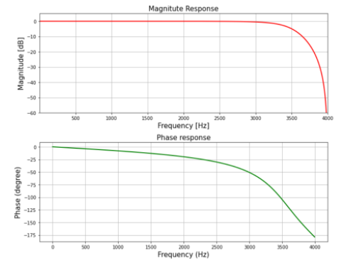
输出:


