Verilog 优先级编码器
在数字系统电路中,编码器是一种组合电路,它采用 2 n条输入信号线并将它们编码成 n 条输出信号线。当使能为真时,即相应的输入信号线显示等效的二进制位输出。
例如,8:3 编码器有 8 条输入线和 3 条输出线,4:2 编码器有 4 条输入线和 2 条输出线,以此类推。
一个 8:3 优先级编码器有 7 条输入线,即 i0 到 i7,以及 3 条输出线 y2、y1 和 y0。在 8:3 优先级编码器中,i7 具有最高优先级,而 i0 具有最低优先级。
真值表:
Input | Output | ||||||||||
|---|---|---|---|---|---|---|---|---|---|---|---|
| en | i7 | i6 | i5 | i4 | i3 | i2 | i1 | i0 | y2 | y1 | y0 |
| 0 | x | x | x | x | x | x | x | x | z | z | z |
| 1 | 0 | 0 | 0 | 0 | 0 | 0 | 0 | 1 | 0 | 0 | 0 |
| 1 | 0 | 0 | 0 | 0 | 0 | 0 | 1 | x | 0 | 0 | 1 |
| 1 | 0 | 0 | 0 | 0 | 0 | 1 | x | x | 0 | 1 | 0 |
| 1 | 0 | 0 | 0 | 0 | 1 | x | x | x | 0 | 1 | 1 |
| 1 | 0 | 0 | 0 | 1 | x | x | x | x | 1 | 0 | 0 |
| 1 | 0 | 0 | 1 | x | x | x | x | x | 1 | 0 | 1 |
| 1 | 0 | 1 | x | x | x | x | x | x | 1 | 1 | 0 |
| 1 | 1 | x | x | x | x | x | x | x | 1 | 1 | 1 |
逻辑符号:

在 Verilog 代码中实现优先级编码器:
大多数编程涉及软件开发和设计,但 Verilog HDL 是一种用于设计电子设计的硬件描述语言。 Verilog 为设计人员提供了基于不同抽象级别的设备设计,这些抽象级别包括:门级、数据流、开关级和行为建模。
行为建模:
行为模型是最高级别的抽象,由于我们使用的是行为模型,我们将使用 if-else 编写代码以确保优先级编码器输入值。通过使用 if 条件,根据优先级分配输出值。
设计模块:行为建模
module priorityencoder_83(en,i,y);
  // decalre
  input en;
  input [7:0]i;
  // store and declare output values
  output reg [2:0]y;
  always @(en,i)
  begin
    if(en==1)
      begin
        // priority encoder
        // if condition to chose
        // output based on priority.
        if(i[7]==1) y=3'b111;
        else if(i[6]==1) y=3'b110;
        else if(i[5]==1) y=3'b101;
        else if(i[4]==1) y=3'b100;
        else if(i[3]==1) y=3'b011;
        else if(i[2]==1) y=3'b010;
        else if(i[1]==1) y=3'b001;
        else
        y=3'b000;
      end
     // if enable is zero, there is
     // an high impedence value.
    else y=3'bzzz;
  end
endmodule
测试台:行为
测试台是一个模拟模块,用于为设计模块提供输入。编写 Testbench 的最佳方法是深入了解真值表。准备好真值表后,在测试台中提供输入值。
module tb;
  reg [7:0]i;
  reg en;
  wire [2:0]y;

  // instantiate the model: creating
  // instance for block diagram
  priorityenoder_83 dut(en,i,y);
  initial
    begin
      // monitor is used to display the information.
      $monitor("en=%b i=%b y=%b",en,i,y);
      // since en and i are input values,
      // provide values to en and i.
      en=1; i=128;#5
      en=1; i=64;#5
      en=1; i=32;#5
      en=1; i=16;#5
      en=1; i=8;#5
      en=1; i=4;#5
      en=1; i=2;#5
      en=1; i=0;#5
      en=0;i=8'bx;#5
      $finish;
    end
endmodule
输出:

数据流建模:
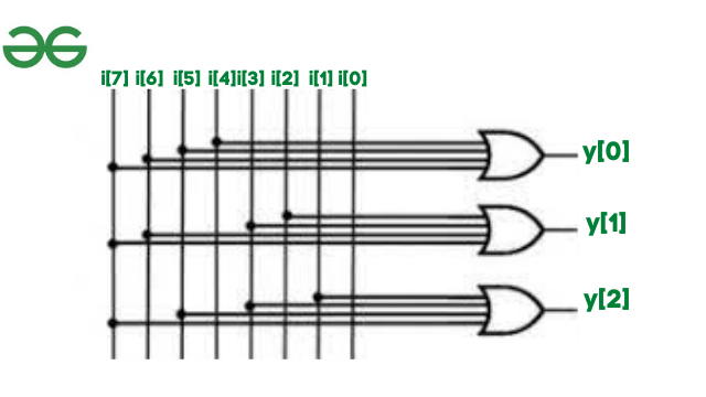
在数据流建模中,我们通过分配输入值来定义输出,即net,即使用分配的关键字进行reg。为了编写数据流建模和门级建模,我们需要一个逻辑图来形成连接。
这是8:3优先级编码器的逻辑图

数据流建模
设计模块:数据流
module priorityenoder83_dataflow(en,i,y);
    // declare port list via input and output
    input en;
    input [7:0]i;
    output [2:0]y;

    // check the logic diagram and assign the outputs
    assign y[2]=i[4] | i[5] | i[6] | i[7] &en;
    assign y[1]=i[2] | i[3] | i[6] | i[7] &en;
    assign y[0]=i[1] | i[3] | i[5] | i[7] &en;

endmodule
测试平台:数据流
module tb;
  reg en;
  reg [7:0]i;
  wire [2:0]y;

  // instantiate the model: creating
  // instance for block diagram
  priorityenoder83_dataflow dut(en,i,y);
  initial
    begin
      // monitor is used to display the information.
      $monitor("en=%b i=%b y=%b",en,i,y);

      // since en and i are input values,
      // provide values to en and i.
      en=1;i=128;#5
      en=1;i=64;#5
      en=1;i=32;#5
      en=1;i=16;#5
      en=1;i=8;#5
      en=1;i=4;#5
      en=1;i=2;#5
      en=1;i=1;#5
      en=0;i=8'bx;#5
      $finish;
    end
endmodule
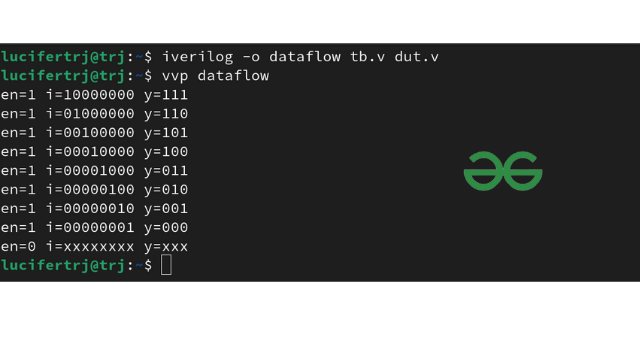
输出:

门级建模:
在门级建模中,我们利用了数字电子学中使用的数字逻辑门。
句法:
logicgate object(out,in1,in2);例子:
and a1(out,a,b);设计模块:门级
module priorityenoder83_gate(en,i,y);
    // declare port list via input and output
    input en;
    input [7:0]i;
    output [2:0]y;

    wire temp1,temp2,temp3; // temp is used to apply
                            // enable for the or gates
    // check the logic diagram and use
    // logic gates to compute outputs
    or o1(temp1,i[4],i[5],i[6],i[7]);
    or o2(temp2,i[2],i[3],i[6],i[7]);
    or o3(temp3,i[1],i[3],i[5],i[7]);

    and a1(y[2],temp1,en);
    and a2(y[1],temp2,en);
    and a3(y[0],temp3,en);

endmodule
测试平台:门级
module tb;
  reg en;
  reg [7:0]i;
  wire [2:0]y;

  // instantiate the model: creating
  // instance for block diagram
  priorityenoder83_gate dut(en,i,y);
  initial
    begin
      // monitor is used to display
      // the information.
      $monitor("en=%b i=%b y=%b",en,i,y);
      // since en and i are input values,
      // provide values to en and i.
      en=1;i=128;#5
      en=1;i=64;#5
      en=1;i=32;#5
      en=1;i=16;#5
      en=1;i=8;#5
      en=1;i=4;#5
      en=1;i=2;#5
      en=1;i=1;#5
      en=0;i=8'bx;#5
      $finish;
    end
endmodule
输出:

优先编码器的应用:
- 机器人车辆
- 医院的健康监测系统