- Verilog Mod-N计数器(1)
- Verilog Mod-N计数器
- Verilog灰色计数器
- Verilog灰色计数器(1)
- Verilog环形计数器(1)
- Verilog环形计数器
- Verilog波纹计数器(1)
- Verilog波纹计数器
- Verilog D闩锁
- Verilog D闩锁(1)
- Verilog Johnson计数器
- Verilog Johnson计数器(1)
- Verilog数组
- Verilog数组(1)
- Verilog函数(1)
- Verilog函数
- 使用 verilog HDL 进行计数器设计
- 使用 verilog HDL 进行计数器设计(1)
- 计数器 +1 python (1)
- 正计数器python(1)
- python中的计数器(1)
- 计数器 javascript (1)
- Verilog模块(1)
- Verilog模块
- Verilog参数(1)
- Verilog参数
- Verilog运算符(1)
- Verilog运算符
- java中的计数器(1)
📅 最后修改于: 2021-01-11 15:11:59 🧑 作者: Mango
4位计数器
4位计数器从4'b0000开始递增到4'h1111,然后又回到4'b0000。只要提供运行时钟,它就会一直计数,并且复位保持高电平。
当最终加法的最高有效位被丢弃时,将发生翻转。当计数器的最大值为4'h1111并收到另一个计数请求时,该计数器尝试达到5'b10000,但由于它只能支持4位,因此MSB将被丢弃,结果为0。
    0000
    0001
    0010
    ...
    1110
    1111
           rolls over
    0000
    0001
    ...
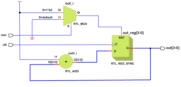
该设计包含两个输入,一个用于时钟,第二个用于低电平有效复位。低电平有效复位是在复位引脚的值为0时复位设计的地方。有一个名为out的4位输出,该输出实质上提供计数器值。
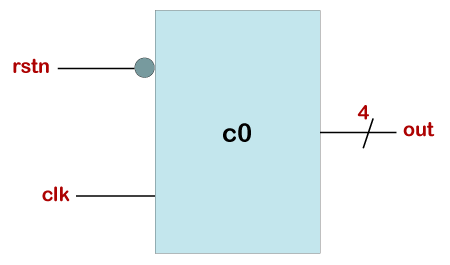
电子柜台实例
module counter (input clk,      // Declare input port for the clock to allow counter to count up
                  input rstn,              // Declare input port for the reset to allow the counter to be reset to 0 when required
                  output reg[3:0] out);    // Declare 4-bit output port to get the counter values

 // This always block will be triggered at the rising edge of clk (0->1)
  // Once inside this block, it checks if the reset is 0, then change out to zero
  // If reset is 1, then the design should be allowed to count up, so increment the counter

  always @ (posedge clk) begin
    if (! rstn)
      out <= 0;
    else
      out <= out + 1;
  end
endmodule
模块计数器具有时钟和低电平有效复位( n )作为输入,计数器值具有4位输出。
每当时钟从0过渡到1时,始终执行块,这表示上升沿或上升沿。
仅当复位保持为高电平或1(由if-else块实现)时,输出才递增。如果在时钟的上升沿复位为低电平,则输出复位为默认值4'b0000。
试验台
我们可以将设计实例化到测试平台模块中,以验证计数器是否按预期进行计数。
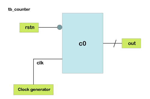
testbench模块名为tb_counter ,并且不需要端口,因为它是仿真中的顶级模块。但是,我们需要具有内部变量来生成,存储和驱动时钟以及复位。
为此,我们为时钟和复位声明了两个类型为reg的变量。我们还需要一个线型网络来与设计的输出建立连接。否则,它将默认为1位标量网络。
时钟是通过Always模块生成的,该模块的周期为10次。初始块用于为我们的内部变量设置初始值,并驱动设计的重置值。
设计在测试平台中实例化,并连接到我们的内部变量,以在我们从测试平台驱动它们时获取值。
我们的测试台中没有任何$ display语句,因此在控制台中将看不到任何消息。
module tb_counter;
  reg clk;                     // Declare an internal TB variable called clk to drive clock to the design
  reg rstn;                    // Declare an internal TB variable called rstn to drive active low reset to design
  wire [3:0] out;              // Declare a wire to connect to design output

  // Instantiate counter design and connect with Testbench variables
  counter   c0 ( .clk (clk),
                 .rstn (rstn),
                 .out (out));

  // Generate a clock that should be driven to design
  // This clock will flip its value every 5ns -> time period = 10ns -> freq = 100 MHz

 always #5 clk = ~clk;

  // This initial block forms the stimulus of the testbench
  initial begin
    // Initialize testbench variables to 0 at start of simulation
    clk <= 0;
    rstn <= 0;

    // Drive rest of the stimulus, reset is asserted in between
    #20   rstn <= 1;
    #80   rstn <= 0;
    #50   rstn <= 1;

    // Finish the stimulus after 200ns
    #20 $finish;
  end
endmodule
请注意,当低电平有效复位变为0时,计数器复位为0,并且在约150ns时取消复位时,计数器从下一次出现时钟正沿开始计数。
硬件原理图