- jquery 数字计数器 - Javascript (1)
- jquery 数字计数器 - Javascript 代码示例
- python中的计数器(1)
- 计数器 +1 python (1)
- 正计数器python(1)
- 计数器 javascript (1)
- 数字逻辑中的计数器(1)
- 数字逻辑中的计数器
- java中的计数器(1)
- Python中的计数器 |设置 2(访问计数器)
- Python中的计数器 |设置 2(访问计数器)(1)
- 正计数器python代码示例
- python代码示例中的计数器
- 计数器 +1 python 代码示例
- 计数器 javascript 代码示例
- java代码示例中的计数器
- python中的计数器方法(1)
- python代码示例中的计数器方法
- 数字电子产品中的计数器(1)
- 数字电子产品中的计数器
- 数字逻辑中的非二进制计数器
- 数字逻辑中的非二进制计数器
- 数字逻辑中的非二进制计数器(1)
- python 计数器 - Python (1)
- python ++ 计数器 - Python (1)
- python中的时间计数器(1)
- 单词计数器 c# (1)
- python ++ 计数器 - Python 代码示例
- python 计数器 - Python 代码示例
📅 最后修改于: 2021-01-12 04:56:50 🧑 作者: Mango
计数器是一个时序电路。用于计数脉冲的数字电路是已知的计数器。计数器是触发器的最广泛应用。它是一组施加了时钟信号的触发器。计数器有两种类型。
- 异步或波纹计数器。
- 同步计数器。
异步或波纹计数器
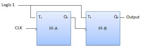
图中显示了一个2位波纹上升计数器的逻辑图。使用了触发器(T)触发器。但是我们也可以将JK触发器与J和K永久连接到逻辑1一起使用。外部时钟应用于触发器A的时钟输入,Q A输出应用于下一个触发器的时钟输入,即FF-B。
逻辑图
操作方式
| S.N. | Condition | Operation |
|---|---|---|
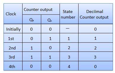
| 1 | Initially let both the FFs be in the reset state | QBQA = 00 initially |
| 2 | After 1st negative clock edge |
As soon as the first negative clock edge is applied, FF-A will toggle and QA will be equal to 1. QA is connected to clock input of FF-B. Since QA has changed from 0 to 1, it is treated as the positive clock edge by FF-B. There is no change in QB because FF-B is a negative edge triggered FF. QBQA = 01 after the first clock pulse. |
| 3 | After 2nd negative clock edge |
On the arrival of second negative clock edge, FF-A toggles again and QA = 0. The change in QA acts as a negative clock edge for FF-B. So it will also toggle, and QB will be 1. QBQA = 10 after the second clock pulse. |
| 4 | After 3rd negative clock edge |
On the arrival of 3rd negative clock edge, FF-A toggles again and QA become 1 from 0. Since this is a positive going change, FF-B does not respond to it and remains inactive. So QB does not change and continues to be equal to 1. QBQA = 11 after the third clock pulse. |
| 5 | After 4th negative clock edge |
On the arrival of 4th negative clock edge, FF-A toggles again and QA becomes 1 from 0. This negative change in QA acts as clock pulse for FF-B. Hence it toggles to change QB from 1 to 0. QBQA = 00 after the fourth clock pulse. |
真相表
同步计数器
如果同时将“时钟”脉冲施加到计数器中的所有触发器,则该计数器称为同步计数器。
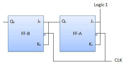
2位同步递增计数器
FF-A的J A和K A输入与逻辑1相关联。因此FF-A将用作触发触发器。 J B和K B输入连接到Q A。
逻辑图
操作方式
| S.N. | Condition | Operation |
|---|---|---|
| 1 | Initially let both the FFs be in the reset state | QBQA = 00 initially. |
| 2 | After 1st negative clock edge |
As soon as the first negative clock edge is applied, FF-A will toggle and QA will change from 0 to 1. But at the instant of application of negative clock edge, QA , JB = KB = 0. Hence FF-B will not change its state. So QB will remain 0. QBQA = 01 after the first clock pulse. |
| 3 | After 2nd negative clock edge |
On the arrival of second negative clock edge, FF-A toggles again and QA changes from 1 to 0. But at this instant QA was 1. So JB = KB= 1 and FF-B will toggle. Hence QB changes from 0 to 1. QBQA = 10 after the second clock pulse. |
| 4 | After 3rd negative clock edge |
On application of the third falling clock edge, FF-A will toggle from 0 to 1 but there is no change of state for FF-B. QBQA = 11 after the third clock pulse. |
| 5 | After 4th negative clock edge |
On application of the next clock pulse, QA will change from 1 to 0 as QB will also change from 1 to 0. QBQA = 00 after the fourth clock pulse. |
柜台分类
根据计数进行的方式,同步或异步计数器分为以下几种:
- 柜台
- 柜台
- 递增/递减计数器
上/下计数器
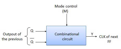
递增计数器和递减计数器结合在一起以获得递增/递减计数器。还提供了模式控制(M)输入以选择上或下模式。为了实现上/下操作,需要在每对触发器之间设计和使用组合电路。
- 加/减计数器的类型
- 上下波动计数器
- 上/下同步计数器
上下波纹计数器
在UP / DOWN纹波计数器中,所有FF都以触发模式运行。因此,将使用T型触发器或JK型触发器。 LSB触发器直接接收时钟。但是,从前一个FF的(Q = Q bar)输出获得每个其他FF的时钟。
-
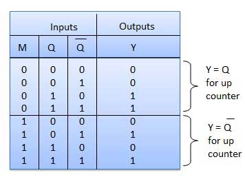
向上计数模式(M = 0) -如果要进行向上计数,则前一个FF的Q输出连接到下一级的时钟。对于此模式,模式选择输入M为逻辑0(M = 0)。
-
向下计数模式(M = 1) -如果M = 1,则前一个FF的Q bar输出连接到下一个FF。这将使计数器在计数模式下运行。
例
3位二进制上下波动计数器。
-
3位-因此需要三个FF。
-
上/下-因此模式控制输入必不可少。
-
对于脉动上升计数器,前一个FF的Q输出连接到下一个FF的时钟输入。
-
对于脉动上升计数器,前一个FF的Q输出连接到下一个FF的时钟输入。
-
对于纹波下降计数器,前一个FF的Q bar输出连接到下一个FF的时钟输入。
-
令前一个FF的Q和Q bar输出的选择由模式控制输入M控制,如果M = 0,则进行UP计数。因此,将Q连接到CLK。如果M = 1,则向下计数。因此,将Q bar连接到CLK。
框图
真相表
操作方式
| S.N. | Condition | Operation |
|---|---|---|
| 1 | Case 1 − With M = 0 (Up counting mode) |
If M = 0 and M bar = 1, then the AND gates 1 and 3 in fig. will be enabled whereas the AND gates 2 and 4 will be disabled. Hence QA gets connected to the clock input of FF-B and QB gets connected to the clock input of FF-C. These connections are same as those for the normal up counter. Thus with M = 0 the circuit work as an up counter. |
| 2 | Case 2: With M = 1 (Down counting mode) |
If M = 1, then AND gates 2 and 4 in fig. are enabled whereas the AND gates 1 and 3 are disabled. Hence QA bar gets connected to the clock input of FF-B and QB bar gets connected to the clock input of FF-C. These connections will produce a down counter. Thus with M = 1 the circuit works as a down counter. |
模数计数器(MOD-N计数器)
2位波纹计数器称为MOD-4计数器,而3位波纹计数器称为MOD-8计数器。因此,通常将n位波纹计数器称为N模计数器。其中,MOD号= 2 n 。
模数类型
- 2位向上或向下(MOD-4)
- 3位向上或向下(MOD-8)
- 4位上下(MOD-16)
柜台申请
- 频率计数器
- 数码时钟
- 时间测量
- 模数转换器
- 分频器电路
- 数字三角波发生器。