Verilog HDL 中的 2 到 4 解码器
在本文中,我们将使用 Verilog HDL 中的所有抽象级别,通过逐步的过程来实现 2:4 解码器。在继续编码之前,我们将查看 2:4 解码器的真值表和逻辑符号。
2:4解码器
解码器是具有“n”条输入信号线和2n条输出线的组合逻辑电路。在 2:4 解码器中,我们有 2 条输入线和 4 条输出线。此外,我们在输入端提供了“ enable ”,以确保解码器在 enable 为 1 时工作,在 enable 为 0 时关闭。真值表、逻辑图和逻辑符号如下所示:
真值表:
| En | Input | Output | ||||
|---|---|---|---|---|---|---|
| a | b | y3 | y2 | y1 | y0 | |
| 1 | x | x | 1 | 1 | 1 | 1 |
| 0 | 0 | 0 | 1 | 1 | 1 | 0 |
| 0 | 0 | 1 | 1 | 1 | 0 | 1 |
| 0 | 1 | 0 | 1 | 0 | 1 | 1 |
| 0 | 1 | 1 | 0 | 1 | 1 | 1 |
逻辑符号:

逻辑图:

与 2:4 解码器类似,3 到 8 解码器产生 8 条输出信号线,4 到 16 解码器产生 16 条输出信号线。
我们现在将在从最高到最低的不同抽象级别中实现 2:4 解码器。
1.行为建模:
行为建模以高抽象级别表示电路。行为建模的语法类似于 C 编程的语法。我们可以使用行为建模在 Verilog 设计块中实现条件语句,如 if、case 语句、循环和结构过程(初始和始终)。
句法:
if(condition)
  true_statement;
else if(condition)
   true_statement;
else
   else_statement
设计模块:行为建模
module decoder24_behaviour(en,a,b,y);
   // input port
   input en,a,b;

   // use reg to store the output value
   output reg [3:0]y;
   // always is used in design block
   // only in Behavioural modeling.

   always @(en,a,b)
     begin
       // using condition if statement
       // implement the 2:4 truth table
       if(en==0)
         begin
           if(a==1'b0 & b==1'b0) y=4'b1110;
           else if(a==1'b0 & b==1'b1) y=4'b1101;
           else if(a==1'b1 & b==1'b0) y=4'b1011;
           else if(a==1 & b==1) y=4'b0111;
           else y=4'bxxxx;
         end
       else
        y=4'b1111;
     end
endmodule
测试平台:行为建模
一旦我们设计了设计块,我们就必须对其进行测试。测试台是一个模拟模块,用于通过应用激励和绕过输入值检查结果来测试设计模块。将设计块视为输出实现,我们只考虑输出结果而不考虑输入。但是在编写测试平台时,您需要提供正确的输入,这里真值表对于声明输入值非常重要。
在 Testbench 中,重要的一步是链接设计块,这是通过实例化完成的:
modulename instance(port list);为了显示结果,我们将使用 $monitor 系统任务。
句法:
$monitor(display_statement);module tb;
// input port are declared in reg(register)
reg a,b,en;
// output port are declared in wire(net)
wire [3:0]y;
// instantiate design block
decoder24_behaviour dut(en,a,b,y);
initial
begin
$monitor("en=%b a=%b b=%b y=%b",en,a,b,y);
// with reference to truth table provide input values
en=1;a=1'bx;b=1'bx;#5
en=0;a=0;b=0;#5
en=0;a=0;b=1;#5
en=0;a=1;b=0;#5
en=0;a=1;b=1;#5
// terminate simulation using $finish system task
$finish;
end
endmodule输出:运行程序:
iverilog -o behavior tb.v dut.v
vvp behavior
注意: iverilog 是运行 Verilog 程序的 Verilog 编译器。 vvp 是运行 Verilog 代码的命令。
2.数据流建模:
在定义数据流建模时,设计人员必须牢记数据在设计描述中的流动方式。随着逻辑综合工具的完善,数据流建模已成为一种广受欢迎的设计方法。在数据流中,我们使用关键字assign来存储净值。
句法:
assign out = expression;设计模块:数据流
module decoder24_assign(en,a,b,y);
    // declare input and output ports
    input en,a,b;
    output [3:0]y;

    // supportive connection required
    wire enb,na,nb;
    assign enb = ~en;
    assign na = ~a;
    assign nb = ~b;

    // assign output value by referring to logic diagram
    assign y[0] = ~(enb&na&nb);
    assign y[1] = ~(enb&na&b);
    assign y[2] = ~(enb&a&nb);
    assign y[3] = ~(enb&a&b);

endmodule
测试台:数据流
module tb;
  // input port are declared in reg(register)
  reg a,b,en;

  // output port are declared in wire(net)
  wire [3:0]y;

  // instantiate design block
  decoder24_assign dut(en,a,b,y);

  initial
    begin
      $monitor("en=%b a=%b b=%b y=%b",en,a,b,y);
      // with reference to truth
      // table provide input values
      en=1;a=1'bx;b=1'bx;#5
      en=0;a=0;b=0;#5
      en=0;a=0;b=1;#5
      en=0;a=1;b=0;#5
      en=0;a=1;b=1;#5
      // terminate simulation using $finish system task
      $finish;
    end
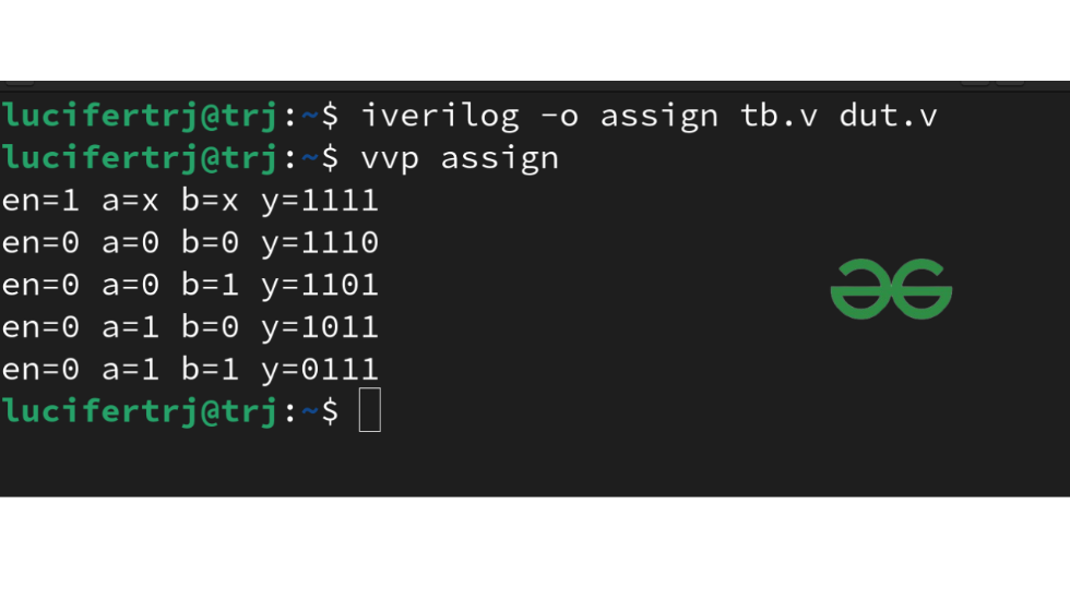
endmodule输出:运行程序:
iverilog -o assign tb.v dut.v
vvp assign
3.门级建模:
逻辑门是逻辑电路的构建块。 Verilog 支持将基本门作为预定义的原语。这些原语被实例化(创建实例/对象)并且可以在模块定义中实现。
句法:
logicgate object(output_port,input_port)例子:
nand n1(y,x1,x2)注意:逻辑门是小写的,对象可以是关键字以外的任何名称。在上面的例子中,y是输出,x1和x2是输入信号。
Verilog 代码从模块定义开始,输入和输出端口作为参数传递。借助逻辑图,我们将实例化 4 个 NAND 门和 3 个 NOT 门来连接输入和输出信号以实现 2:4 解码器。
设计模块:门级
module decoder24_gate(en,a,b,y);
    // declare input and output ports
    input en,a,b;
    output [3:0]y;

    // supportive connections required
    // to connect nand gates
    wire enb,na,nb;

    // instantiate 4 nand gates and 3 not gates
    // make connections by referring the above logic diagram
    not n0(enb,en);
    not n1(na,a);
    not n2(nb,b);

    nand n3(y[0],enb,na,nb);
    nand n4(y[1],enb,na,b);
    nand n5(y[2],enb,a,nb);
    nand n6(y[3],enb,a,b);

endmodule
测试台:门级
module tb;
  // input port are declared in reg(register)
  reg a,b,en;
  // output port are declared in wire(net)
  wire [3:0]y;
  // instantiate design block
  decoder24_gate dut(en,a,b,y);

  initial
    begin
      $monitor("en=%b a=%b b=%b y=%b",en,a,b,y);
      // with reference to truth table provide input values
      en=1;a=1'bx;b=1'bx;#5
      en=0;a=0;b=0;#5
      en=0;a=0;b=1;#5
      en=0;a=1;b=0;#5
      en=0;a=1;b=1;#5
      // terminate simulation using $finish system task
      $finish;
    end
endmodule输出:运行程序:
iverilog -o gate tb.v dut.v
vvp gate
解码器的应用:
以下是在现实世界中实现解码器的一些领域:
- 代码转换器
- 带金属探测器的机器人车
- 基于射频的家庭自动化系统
- 用于 CPU 的 ALU
- 工业中多台电机的速度同步