使用 Verilog HDL 的全加器
在本文中,我们将讨论使用 Verilog HDL 的 Full Adder 的概述部分。目标是理解这个概念并将使用 Verilog HDL 代码实现 Full Adder。让我们一一讨论。
先决条件-数字逻辑中的全加器
问题陈述 :
编写一个 Verilog HDL 来设计一个全加器。让我们逐步讨论如下。
第1步 :
概念 -
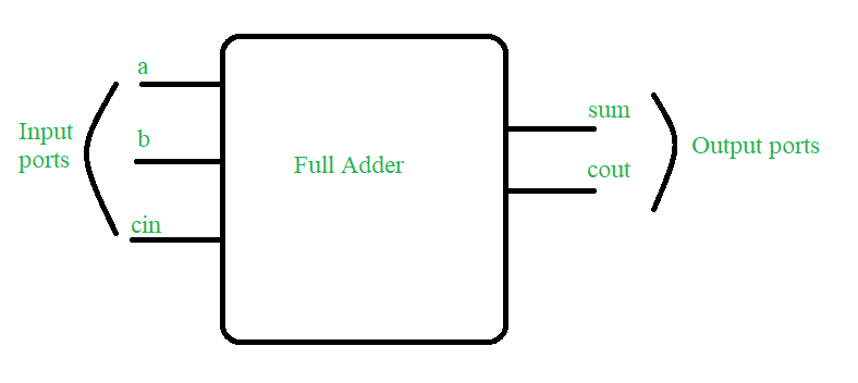
全加器是一个数字组合电路,它具有三个输入 a、b 和 cin 以及两个输出 sum 和 cout。下面绘制真值表以显示全加器的功能。

图为设计要求框图:全加器
第2步 :
真值表——a b cin sum cout 0 0 0 0 0 0 0 1 1 0 0 1 0 1 0 0 1 1 0 1 1 0 0 1 0 1 0 1 0 1 1 1 0 0 1 1 1 1 1 1
第 3 步:
全加器的 Verilog HDL 代码(设计部分)——
// Code your design : Full Adder
module full_add(a,b,cin,sum,cout);
  input a,b,cin;
  output sum,cout;
  wire x,y,z;

// instantiate building blocks of full adder
  half_add h1(.a(a),.b(b),.s(x),.c(y));
  half_add h2(.a(x),.b(cin),.s(sum),.c(z));
  or o1(cout,y,z);
endmodule : full_add

// code your half adder design
module half_add(a,b,s,c);
  input a,b;
  output s,c;

// gate level design of half adder
  xor x1(s,a,b);
  and a1(c,a,b);
endmodule :half_add
第4步 :
试验台 -
// Code your testbench here
module full_add_tb;
  reg a,b,cin;
  wire sum,cout;

// instantiate the DUT block
  full_add f1(.a(a),.b(b),.cin(cin),.sum(sum),.cout(cout));

// this particular line is added to dump the file on online simulator
  initial begin $dumpfile("full_tb.vcd");$dumpvars(); end

// insert all the inputs
  initial begin a=1'b1;  #4; a=1'b0;#10 $stop();end
  initial begin b=1'b1; forever #2 b=~b;end
  initial begin cin=1'b1;forever #1 cin=~cin; #10 $stop();end

// monitor all the input and output ports at times
// when any of the input changes its state

 initial begin $monitor(" time=%0d A=%b B=%b
                          Cin=%b Sum=%b Cout=%b",$time,a,b,cin,sum,cout);end
 endmodule : full_add_tb
第 5 步:
预期产出——
time=0 A=1 B=1 Cin=1 Sum=1 Cout=1
time=1 A=1 B=1 Cin=0 Sum=0 Cout=1
time=2 A=1 B=0 Cin=1 Sum=0 Cout=1
time=3 A=1 B=0 Cin=0 Sum=1 Cout=0
time=4 A=0 B=1 Cin=1 Sum=0 Cout=1
time=5 A=0 B=1 Cin=0 Sum=1 Cout=0
time=6 A=0 B=0 Cin=1 Sum=1 Cout=0
time=7 A=0 B=0 Cin=0 Sum=0 Cout=0
time=8 A=0 B=1 Cin=1 Sum=0 Cout=1
time=9 A=0 B=1 Cin=0 Sum=1 Cout=0
time=10 A=0 B=0 Cin=1 Sum=1 Cout=0
time=11 A=0 B=0 Cin=0 Sum=0 Cout=0
time=12 A=0 B=1 Cin=1 Sum=0 Cout=1
time=13 A=0 B=1 Cin=0 Sum=1 Cout=0