Verilog HDL 中的 4 位纹波进位计数器
要继续 Verilog 代码,我们首先要了解 4 位纹波计数器的结构。顶部设计块由四个 T 型触发器组成。暂时忽略T-Flip Flop的输入输出。让我们考虑一下 Ripple Counter 的整体外部结构。我们有两个输入,即时钟和复位,q 是输出。输出 q 为 4 位向量形式。
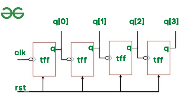
4位纹波进位计数器
在纹波进位计数器中,首先,时钟信号通过第一个 T 触发器。对于第二个 T 型触发器,第一个 T 型触发器的输出充当时钟,依此类推。所有 T 触发器的复位都是相同的。
现在让我们实现涟漪计数器块。
module ripplecounter(clk,rst,q);
  input clk,rst;
  output [3:0]q;

  // initiate 4 T-FF to update the count
  tff tf1(q[0],clk,rst);
  tff tf2(q[1],q[0],rst);
  tff tf3(q[2],q[1],rst);
  tff tf4(q[3],q[2],rst);
endmodule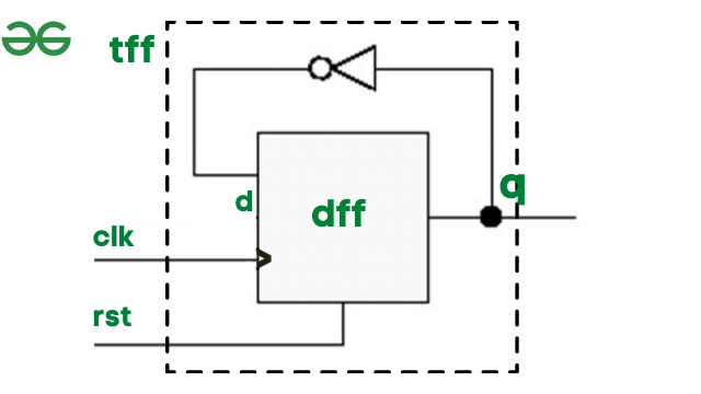
由于我们在ripplecounter中实例化了tff,现在让我们看看T Flip Flop的内部。在 T 触发器内部,我们有一个 D 触发器和一个反相器,即不是门。为了实现 T 触发器,我们需要实例化 d 触发器,我们将 clk 和 reset 作为输入,将 q 作为输出。我们需要一根额外的导线 d,它进一步充当 D 触发器的输入。
module tff(q,clk,rst);
  // tff takes clk and reset as input
  // q is output
  input clk,rst;
  output q;
  wire d;
  // by referring the diagram of tff,
  // instantiate d flip flop and not gate
  dff df1(q,d,clk,rst);
  not n1(d,q);
endmodule
D触发器真值表供参考:
| clk | rst | d | q |
|---|---|---|---|
| ⇡ | 1 | x | 0 |
| ⇡ | 0 | 0 | 0 |
| ⇡ | 0 | 1 | 1 |
设计块:
module ripplecounter(clk,rst,q);
  input clk,rst;
  output [3:0]q;

  // initiate 4 T-FF to update the count
  tff tf1(q[0],clk,rst);
  tff tf2(q[1],q[0],rst);
  tff tf3(q[2],q[1],rst);
  tff tf4(q[3],q[2],rst);
endmodule

module tff(q,clk,rst);
  // tff takes clk and reset as input
  // q is output
  input clk,rst;
  output q;
  wire d;
  // by referring the diagram of tff,
  // instantiate d flip flop and not gate
  dff df1(q,d,clk,rst);
  not n1(d,q);
endmodule

module dff(q,d,clk,rst);
  input d,clk,rst;
  output q;
  reg q; // store the output value
  always @(posedge clk or posedge rst)
   begin
    // refer the truth table to provide
    // values to q based on reset.
    if(rst) q=1'b0;
    else q=d;
   endripplecounter
endmodule
试验台:
仿真用于通过向 dut 提供输入值来验证设计块。我们需要参考ripplecounter块编写测试台,其中我们有clk和reset作为输入。
时钟需要在特定时间单位后切换,因此我们最初将 clk 设置为 0。然后在每 5 个时间单位后,我们在 always 块下将时钟从 0 切换到 1,反之亦然。
initial
 clk=0;
always
 #5 clk=~clk;
这是ripplecounter的模拟:
module tb;
    // input to be stored in reg and output as net(wire)
    reg clk;
    reg rst;
    wire [3:0]q;

    // instantiate the ripplecounter design block
    ripplecounter dut(clk,rst,q);

    // generate clock pulse
    // initially provide 0
    // then inside always block toggle
    // clock every 5 time units
    initial
      clk = 0;
    always
      #5 clk = ~clk;

    // provide reset values as the input
    initial
       begin
         rst = 1;
         #15 rst = 0;
         #180 rst = 1;
         #10 rst = 1;
         #20 $finish;
       end
       initial
        $monitor("time=%g,rst=%b,clk=%b,q=%d",$time,rst,clk,q);
endmodule
输出:

可以看出,当reset为0时,输出q有计数器输出更新,计数。